


Table of Contents
Introduction
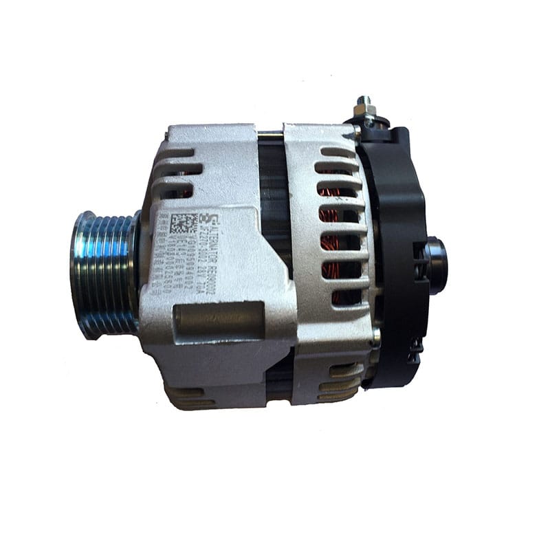
A truck alternator has a straightforward job on paper: convert mechanical energy from the running engine into electrical energy. In practice, however, that single component supports an entire network of lighting, control, monitoring, starting-support, and cabin systems.
Once the engine is running, the truck alternator becomes one of the central components responsible for maintaining the vehicle’s electrical supply and supporting the battery. If charging-system performance becomes unstable, the symptoms may appear in places that seem unrelated to the alternator. Headlights can change intensity, electrical equipment may behave irregularly, warning indicators can appear, or the battery may repeatedly struggle to support starting.
That does not mean every electrical symptom indicates a failed alternator.
The alternator operates together with the battery, starter, wiring, grounding points, drive belt, pulleys, control circuits, connectors, and electrical loads. The truck electrical system should therefore be inspected as an interconnected system.
Understanding how these components interact makes truck alternator diagnosis, identification, and maintenance considerably more systematic.
What Is a Truck Alternator?
A truck alternator is an engine-driven electrical generator.
Its basic purpose is to convert mechanical rotation from the engine into electrical energy while the engine is operating. That electrical energy supports the truck’s active electrical systems and helps maintain the battery in a suitable operating condition.
An automotive alternator generates alternating current internally through electromagnetic induction. Rectifier components then convert that electrical output into direct current suitable for the vehicle’s electrical system.
This is an important distinction.
The alternator does not simply “send electricity” from the engine. It performs several coordinated processes:
mechanical rotation → magnetic field movement → electrical generation → rectification → voltage regulation → vehicle electrical supply.
Each stage depends on specific internal and external components.
If the belt cannot rotate the alternator correctly, electrical generation can be affected. If the rectifier has a problem, generated current may not be converted properly. If wiring or grounding is poor, normal alternator output may not reach the rest of the truck efficiently.
For that reason, alternator diagnosis should consider both the unit itself and the system around it.
How a Truck Alternator Generates Electricity
The operating principle of a truck alternator begins with rotation.
The engine drives the alternator through a belt and pulley system. As the alternator pulley rotates, it turns an internal rotor.
The rotor creates a rotating magnetic field.
Surrounding the rotor is the stator, which contains stationary windings. As the rotor’s magnetic field moves relative to these windings, electrical voltage is induced in the stator.
The electricity initially generated inside the alternator is alternating current.
A rectifier assembly containing diodes then converts this alternating current into direct current that can be used by the truck’s electrical system.
A voltage regulator manages the alternator’s field current so that electrical output remains controlled as engine speed and electrical demand change.
This process happens continuously whenever the alternator is operating.
The simplified sequence is:
engine rotation → belt → pulley → rotor → magnetic field → stator → rectifier → regulator → electrical system.
Understanding this sequence is useful during troubleshooting because a problem can occur at either the mechanical-input side or the electrical-output side.
Main Components Inside a Truck Alternator
| Component | Main Function | Typical Inspection Focus |
|---|---|---|
| Rotor | Creates the rotating magnetic field | Winding condition, internal electrical continuity |
| Stator | Generates electrical current through induction | Windings, insulation, internal damage |
| Rectifier | Converts AC output into DC | Diodes, electrical stability |
| Voltage regulator | Controls alternator output | Output regulation and electrical behavior |
| Bearings | Support rotor rotation | Noise, play, smooth movement |
| Pulley | Transfers belt-driven rotation | Wear, alignment, surface condition |
| Housing | Supports and protects internal parts | Cracks, mounting condition, contamination |
| Cooling components | Manage internal heat | Airflow, contamination, obstruction |
| Electrical terminals | Connect alternator to vehicle circuits | Tightness, contamination, heat damage |
The table illustrates why a truck alternator can develop both mechanical and electrical symptoms.
Bearing wear may create noise even while electrical output remains normal. A regulator problem can affect electrical behavior without producing noticeable mechanical noise.
That difference is useful during diagnosis.
How the Alternator, Battery, and Starter Work Together
The alternator, battery, and starter are closely connected, but they perform different jobs.
The battery stores electrical energy and provides the large initial electrical supply needed when the engine is not running.
When the driver starts the truck, the starter uses electrical energy from the battery to rotate the engine.
Once the engine begins running, the alternator starts generating electrical energy.
At that point, the charging system supports active electrical loads while maintaining the battery.
The operating sequence can therefore be viewed as:
battery → starter → engine starts → alternator operates → electrical system remains supplied.
This relationship explains why charging-system problems can eventually become starting problems.
If the truck alternator does not maintain the electrical system correctly during operation, the battery may gradually become less capable of supporting the next engine start.
However, a starting problem should not automatically be blamed on the alternator.
Battery condition, starter condition, terminals, cables, ground connections, control circuits, and mechanical engine factors can all influence starting behavior.
Good diagnosis separates each stage rather than treating the three components as interchangeable.
Why Alternator Output Changes With Electrical Demand
A truck does not use the same amount of electrical energy at every moment.
Electrical demand changes as different systems operate.
Headlights, marker lamps, cabin lighting, control modules, ventilation systems, wipers, instrumentation, sensors, communication equipment, and other electrical components can all contribute to the total load.
As electrical demand changes, the charging system must respond.
Engine speed also changes continuously. The alternator rotates more slowly near idle and more quickly as engine speed rises.
The voltage regulator helps manage these changing conditions by controlling the magnetic field inside the alternator.
This is why charging-system evaluation should consider operating conditions.
A system may appear normal with minimal electrical loads and behave differently when several electrical functions operate simultaneously.
Likewise, an intermittent problem may appear only at certain engine speeds.
Recording when the symptom occurs can therefore provide more useful information than simply stating that “the alternator is not working correctly.”
Common Signs a Truck Alternator Needs Inspection
Charging-system problems can produce several types of symptoms.
A charging warning indicator is one of the clearest reasons to inspect the system, but it should be treated as a starting point rather than a complete diagnosis.
Lighting behavior can provide additional clues.
Headlights or cabin lights that repeatedly change intensity may indicate unstable electrical conditions. However, poor ground connections, loose wiring, battery problems, or connector resistance can create similar effects.
Repeated difficulty starting after the truck has been operating may also justify charging-system inspection.
Unusual mechanical sound near the alternator deserves attention as well. Bearing wear, pulley issues, belt problems, or mounting conditions can create noise even when electrical generation has not completely stopped.
Other symptoms may include:
- irregular warning indicators
- intermittent electrical functions
- unstable lighting
- repeated battery discharge
- electrical behavior that changes with engine speed
- unusual belt noise
- alternator-area vibration
- connector heating
- abnormal bearing sound
None of these signs should be interpreted in isolation.
The goal is to use symptoms to identify which part of the charging system requires testing.
Why Alternator Problems Are Not Always Alternator Failures
One of the most useful principles in electrical diagnosis is that a symptom at the alternator does not always originate inside the alternator.
Consider the mechanical drive system first.
If the belt slips, the alternator pulley may not rotate consistently with the engine. Electrical output can then become unstable even if the alternator itself remains functional.
Now consider the electrical path.
An alternator can generate suitable output internally, but a damaged cable or poor terminal connection can prevent that output from reaching the battery and other electrical systems correctly.
Grounding problems can create similar symptoms.
Battery condition also influences charging-system behavior. A battery with internal problems can place unusual demands on the alternator or create confusing test results.
The system can therefore be divided into four diagnostic areas:
mechanical drive, alternator, electrical connections, and battery/load system.
Inspecting all four areas prevents the alternator from becoming the automatic explanation for every charging-related symptom.
How to Diagnose a Truck Alternator Systematically
A structured diagnostic process begins with the symptom.
First, determine what actually changed.
Is there a warning indicator? Does the engine start inconsistently? Do lights change intensity? Is there unusual noise? Does the issue appear only after extended operation?
Second, check the mechanical drive.
Inspect the alternator belt, pulley, tensioning components, and visible mounting condition.
Third, consider battery condition.
A charging-system test is difficult to interpret correctly when the battery itself has significant problems.
Fourth, inspect the electrical connections.
Check alternator terminals, battery connections, relevant cables, connectors, and grounding points.
Fifth, evaluate charging-system output using suitable testing procedures and specifications for the particular truck.
Only after these external conditions have been considered should internal alternator failure become the main conclusion.
The sequence is:
symptom → drive system → battery → connections → electrical output → alternator.
This diagnostic order reduces unnecessary assumptions.
Why Wiring and Ground Connections Matter
Electrical current needs a complete circuit.
The positive side carries electrical energy toward vehicle systems, while the return path completes the circuit.
Any significant resistance introduced by loose, contaminated, damaged, or overheated connections can change how the system behaves.
A terminal may look connected while still making poor electrical contact.
Repeated vibration can gradually loosen connections. Moisture and contamination can affect exposed surfaces. Mechanical stress can damage cable strands internally even when the outer insulation appears acceptable.
Ground connections deserve equal attention.
Poor grounding can create unusual symptoms because several electrical systems may share related return paths.
Possible signs include unstable lighting, inconsistent instrument behavior, unusual electrical interaction between circuits, or heat around connection points.
When inspecting a truck alternator, technicians should therefore examine the entire high-current connection path rather than only the alternator terminal.
A functioning alternator cannot compensate fully for a poor electrical connection between itself and the rest of the vehicle.
How Belt Condition Affects Truck Alternator Operation
The alternator depends on mechanical energy from the engine, and the drive belt provides that connection.
If the belt cannot transmit rotation reliably, alternator performance can change.
Belt tension is one important factor.
Insufficient tension can allow slipping, particularly when electrical demand increases and the alternator requires more mechanical input.
Excessive tension is not desirable either because unnecessary loading can affect bearings and related drive components.
Pulley alignment also matters.
If pulleys are not aligned correctly, the belt may track unevenly, generate noise, or experience abnormal wear.
The belt itself should be inspected for cracking, surface deterioration, contamination, unusual glazing, damaged ribs, or other signs of abnormal operation.
Tensioners and idlers should also be considered where fitted.
A truck alternator inspection should therefore include the complete mechanical drive path:
belt → tensioner → pulleys → alternator.
Ignoring the belt can turn an external mechanical problem into an incorrect electrical diagnosis.
How to Identify the Correct Truck Alternator
Accurate truck alternator identification requires more than knowing the general truck model.
Begin with the engine and electrical configuration.
Record the existing alternator’s OEM reference or other readable identification whenever possible.
Then compare physical interfaces.
Important characteristics can include:
- mounting-ear arrangement
- mounting-hole position
- pulley design
- pulley diameter
- belt configuration
- electrical terminal arrangement
- connector shape
- terminal position
- housing dimensions
- rotation requirements
- electrical-system specification
The mounting bracket is particularly important because an alternator that cannot align correctly with the belt system should not be considered compatible.
Electrical terminals deserve equal attention.
Two alternators may mount similarly while using different electrical connections or control arrangements.
The strongest identification process therefore combines:
truck and engine information + OEM reference + mechanical interfaces + electrical interfaces.
Why Similar-Looking Alternators May Not Be Interchangeable
Alternators often share a recognizable overall shape.
A pulley sits at the front, mounting ears surround the housing, and electrical connections are positioned toward the rear.
That similarity can make visual identification misleading.
Two alternators may differ in pulley position by only a small amount, yet that difference can affect belt alignment.
Mounting-ear spacing may also vary.
Terminal locations, connector types, internal regulators, and electrical characteristics can differ while the outer housing appears nearly identical.
Even pulley design matters.
Different belts require different groove configurations, and the pulley must align correctly with the rest of the accessory drive.
This is why physical appearance should be treated only as supporting evidence.
Before considering two units interchangeable, compare the component reference and all important mechanical and electrical interfaces.
If one critical interface differs, compatibility should be investigated further rather than forcing the component into the application.
What to Check Before Installing a Truck Alternator
Before installing a truck alternator, inspect the surrounding system.
Start with the mounting bracket.
Check for cracks, distortion, loose hardware, contamination, or damage that could prevent proper alignment.
Inspect the belt and associated pulleys.
Installing a replacement alternator without investigating an already damaged belt or misaligned pulley can allow the original problem to continue.
Electrical cables and connectors should also be examined carefully.
Look for loose terminals, damaged insulation, contamination, discoloration, or evidence of excessive heat.
Battery connections and relevant ground points should be in suitable condition.
Then compare the alternator with the removed unit.
Confirm the mounting geometry, pulley position, connector arrangement, terminals, housing dimensions, and OEM identification.
The component should align naturally with the bracket.
If substantial force is necessary simply to make the mounting holes line up, the identification or surrounding structure should be rechecked.
Correct installation begins with correct fitment.
How to Verify Operation After Installation
Installing the truck alternator is only part of the job.
The charging system should be checked after installation to confirm that the mechanical and electrical connections work together correctly.
Begin with a visual inspection.
Confirm that mounting fasteners are secure, wiring is correctly connected, terminals are protected, and the belt sits properly in the pulley grooves.
Observe belt tracking when the engine operates.
The belt should run consistently without abnormal movement or noise.
Listen around the alternator for unexpected bearing, pulley, or belt sounds.
Electrical operation should then be evaluated using suitable equipment and the applicable vehicle specifications.
Check warning indicators and observe the electrical system under different operating conditions.
Several electrical loads can be activated to determine whether the system remains stable as demand changes.
After an initial operating period, inspect connectors and terminals again for looseness, abnormal heat, or other changes.
Verification ensures that installation has solved the problem rather than simply replaced a component.
Preventive Maintenance for Truck Charging Systems
Alternator reliability depends heavily on the condition of the systems around it.
Periodic belt inspection can reveal cracking, unusual wear, contamination, or alignment problems before rotation becomes inconsistent.
Electrical terminals should remain secure and clean.
High-current cables deserve particular attention because small connection problems can create significant resistance and heat.
Grounding points should also remain mechanically secure.
The alternator housing and cooling areas should not become heavily blocked by contamination that interferes with heat dissipation.
Mounting fasteners should remain tight enough to hold the alternator correctly aligned with the belt system.
Battery condition should form part of the same maintenance process.
Charging and energy storage operate together, so repeatedly examining one while ignoring the other produces an incomplete picture.
Maintenance records can help identify patterns.
Repeated belt problems, connector heating, charging irregularities, or battery symptoms may point toward a system-level condition that a single component inspection would miss.
A Practical Five-Point Truck Alternator Check
A simple maintenance framework can make charging-system inspection more consistent.
Use the five-point DRIVE check:
Drive examines the belt, pulley, tensioning system, and mechanical rotation.
References confirms the OEM number, mounting application, electrical configuration, and component identity.
Interfaces checks mounting points, connectors, terminals, and ground paths.
Voltage behavior evaluates charging-system operation according to the applicable vehicle specifications.
Environment looks for heat, contamination, vibration, damaged wiring, and surrounding conditions that could affect the alternator.
The purpose of this framework is not to replace proper testing.
It is to ensure that technicians do not focus so narrowly on the alternator that they miss the mechanical or electrical conditions surrounding it.
A charging system works as a circuit and a mechanical drive system at the same time.
Inspection should reflect both.
Common Truck Alternator Maintenance Mistakes
One common mistake is replacing an alternator before checking the belt.
Another is testing electrical output while ignoring loose battery or ground connections.
Visual matching creates another risk during component identification. Similar housing shapes can hide meaningful differences in mounting points, pulley geometry, connectors, or internal electrical configuration.
Ignoring repeated failures is also problematic.
If more than one alternator develops similar symptoms on the same truck, the surrounding system deserves careful investigation. Belt tension, electrical connections, battery condition, vibration, contamination, and electrical demand may all provide useful clues.
Another mistake is assuming that every battery-related symptom originates with the alternator.
The battery and charging system influence each other, so both need to be evaluated logically.
Finally, installation should never end before functional verification.
A truck alternator may fit correctly and rotate normally while an electrical connection remains incomplete.
Mechanical fitment and electrical performance both need confirmation.
Conclusion
A truck alternator converts mechanical energy from the running engine into electrical energy that supports the vehicle’s electrical systems and helps maintain the battery.
Its operation depends on several internal components, including the rotor, stator, rectifier, regulator, bearings, and pulley. Just as importantly, it depends on external systems such as the drive belt, battery, cables, connectors, grounding points, and electrical loads.
That is why reliable diagnosis should follow a system-based process.
Begin with the symptom, inspect the mechanical drive, evaluate the battery and connections, assess electrical behavior, and only then narrow the diagnosis to the alternator itself.
When selecting a truck alternator, combine OEM references with engine information, mounting geometry, pulley design, and electrical interfaces.
This approach makes identification more accurate and helps ensure that the real cause of a charging-system problem is addressed rather than simply replacing the most visible component.
FAQ
What does a truck alternator do?
A truck alternator converts engine-driven mechanical rotation into electrical energy while the engine is running. It supports active electrical systems and helps maintain the battery. Its operation depends on the belt drive, internal generator components, wiring, grounding, and electrical loads.
What are common signs of a truck alternator problem?
Charging warnings, unstable lighting, repeated battery discharge, electrical behavior that changes with engine speed, unusual bearing or belt noise, and intermittent electrical functions can justify inspection. These symptoms can also originate from wiring, battery, belt, or grounding problems.
How can I identify the correct truck alternator?
Start with the truck and engine configuration, then record the existing OEM reference. Compare mounting ears, bolt positions, pulley design, belt arrangement, electrical terminals, connectors, housing dimensions, and relevant electrical specifications before confirming compatibility.
Can a bad belt cause truck alternator symptoms?
Yes. A loose, worn, contaminated, or incorrectly aligned belt can prevent the alternator pulley from receiving stable engine rotation. Similar symptoms can also result from tensioner or pulley problems, so the complete accessory-drive system should be inspected during charging-system diagnosis.
Why can two truck alternators that look similar be different?
Similar housings can hide differences in mounting geometry, pulley alignment, terminal layout, connectors, regulators, or electrical configuration. Visual appearance can support identification, but OEM references and mechanical and electrical interfaces provide more reliable compatibility evidence.
Need Help Choosing the Right Truck Alternator?
If you’re unsure which truck alternator matches your engine, electrical configuration, mounting system, pulley arrangement, or OEM reference, our team can help review component markings and fitment information. Contact our truck electrical parts team for professional alternator compatibility support.